Product Details
Product Description
Product Description
Focus on DCS, PLC, robot control system and large servo system.
Main products: various modules / cards, controllers, touch screens, servo drivers.
Advantages: supply of imported original products, professional production parts,
Fast delivery, accurate delivery time,
The main brands include ABB Bailey, Ge / fuanc, Foxboro, Invensys Triconex, Bently, A-B Rockwell, Emerson, ovation, Motorola, xyvom, Honeywell, Rexroth, KUKA, Ni, Deif, Yokogawa, Woodward, Ryan, Schneider, Yaskawa, Moog, prosoft and other brands
| GDB021BE05 HIEE300766R0005 |
TE: To prevent possible signal degradation, use a separate metal conduit run for both the sensor and signal/power wiring. Transmitter power passes through the signal leads. Under ideal conditions, the use of conduit and shielded wire may not be required. However, to avoid noise problems, enclose the sensor and signal/power wiring in separate conduit. Just prior to entering the housing, terminate rigid conduit and install a short length of flexible conduit to reduce any stress to the housing. Signal/power wiring must bear a suitable voltage rating, a temperature rating of 75-degrees Celsius (167-degrees Fahrenheit), and must be in accordance with all NEC requirements for the installation site. OTHER EQUIPMENT INTERFACE The transmitter has an isolated output and controls the loop current between four and 20 milliamperes depending on the range and PV values. Since the output is isolated, the instrument loop may have a maximum of one nonisolated device within its circuit. The maximum load on the current loop must not exceed the values shown in Figure 1-1. TRANSMITTER ROTATION The transmitter has four pairs of threaded mounting holes. Since these holes are located at the corners of the transmitter, it can be mounted in any of the four positions as shown in Figure 3-2. INSTALLATION SEQUENCE Refer to Figure 3-3 for the transmitter installation sequence. Each block of the flow represents a single task that must be completed before continuing with the sequence. In some cases, more than one path can be taken during installation. For paths that are in parallel, either complete all of the tasks in all of the paths before continuing or complete all of the tasks in only those paths that apply before continuing. At least one path must be completed. Some blocks contain alphanumeric codes. These codes identify the procedure that describes the steps to complete an INSTALLATION INSTALLATION SEQUENCE 3 - 4 WTPEEUI520002A1 indicated task. Complete all of the steps given in a procedure before continuing to the next procedure. The procedures have check boxes in the margin by each procedural step. When performing a procedure, check each box as each step is completed. By treating each task as a separate entity, the procedures provide an easy method for finding the information needed to perform each task in the installation sequence. Figure 3-2. Transmitter Rotation N O R OTAT IO N 90 R OTAT IO N o 2 70 R OTAT IO N o 180 R OTAT IO N o T03432A Figure 3-3. Installation Sequence TR4027A MOUNTING SCHEME? S TA RT HINGE WALL PA N E L PIPE DONE WIRING AND GROUNDING WALL PR5 MOUNTING PIPE MOUNTING HINGE MOUNTING PA N E L MOUNTING PR3 PR1 PR4 PR2 INTRODUCTION WTPEEUI520002A1 4 - 1 SECTION 4 - OPERATING PROCEDURES INTRODUCTION The Type TB82TE transmitter has six main operating modes: measure, calibrate, output/hold, configure, security, and secondary display. An operating mode has several programming states that contain functions specific to that mode. The transmitter has a built-in user interface through which all transmitter functions are programmed or monitored. In order to maximize the viewing area and minimize the space needed for the keypad, the patent-pending interface uses a custom LCD and four-button keypad. Instrument functions and programming prompts are available through two regions on the LCD. These regions include a primary area that shows the PV (conductivity) and a secondary area that displays text prompts for programming or auxiliary information. In addition to the user friendly interface, the transmitter has a group of icons that alert the user of an existing fault condition, diagnostic spike output, or a held output. These icons, located at the top of the LCD, only appear under the specified condition. Pressing the FAULT info smart key while in the measure mode allows interrogation of any fault condition.
>>
Laser Welding Machine Metal Fiber Handheld
>>
wholesale Beverage stand up pouch plastic bag with spout, fruit juice stand pouch packaging bag
>>
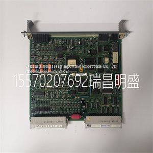
Module spare parts GDB021BE05 HIEE300766R0005
>>
CNC/Mnc CE Approved Gooda Manufacturer 4mm Cutting for Sigle Side High Precision Metaworking Processing with Factory Price Th-1200nca
>>
Wholesale Cheap Price Overgrip Double Layer PU Leather Colorful Anti Slip Badminton Tennis Overgrip
>>
High quality front hood gas spring gas strut for BMW 1 (E81 E82) 2006-2012
>>
Self-Generating Commercial Running Cardio Fitness Training Curved Treadmill for Gym Home Use
>>
Belon Power 10kw three phase 380v gasoline generator 10kw three phase petrol generator
>>
Dia 4.8mm High carbon PC steel wire in coil (Spiral)
>>
Bladen Disc Plough Tractor Mounted Spring Steel 3three Blades Disc Plow Plough
>>
Low Fuel Consumption Little Noise Mr20 2ton Mini Excavator
>>
China Gold Mining Equipment Generator Single Ylinder Diesel Engine for Mine
>>
Mechanical Manufacturing PTFE POM Peek Nylon CNC Milling Parts Plastic
>>
XYLAN COATED FLUOROCARBON COATING GRADE: XYLAN 1070 STUD BOLTS WITH NUTS
>>
Lxd-200 End Milling Machine for Aluminum Profile End Milling, Step Face and Slotprocessing Adjustable Processing Angle Within 35~90°
>>
Thermal Triple Offset Butterfly Valve
>>
Multi Cavity Other Injection Mould Mold Shock Absorber Plastic Products Barrel Manufacture
>>
Relay LRE482 LRE483 CAE31M5 CAE22M5 LRE361 R4343E1014 RM7800L1012
>>
TM-8812 Steel Iron Thickness Gauge Ultrasonic Thickness Measurement Thickness Measuring Equipment
>>
Mh Type 3 Ton 5 Ton 10 Ton 16 Tons Truss Girder Gantry Crane for Sale