Product Details
Product Description
Product Description
Focus on DCS, PLC, robot control system and large servo system.
Main products: various modules / cards, controllers, touch screens, servo drivers.
Advantages: supply of imported original products, professional production parts,
Fast delivery, accurate delivery time,
The main brands include ABB Bailey, Ge / fuanc, Foxboro, Invensys Triconex, Bently, A-B Rockwell, Emerson, ovation, Motorola, xyvom, Honeywell, Rexroth, KUKA, Ni, Deif, Yokogawa, Woodward, Ryan, Schneider, Yaskawa, Moog, prosoft and other brands
GOP2
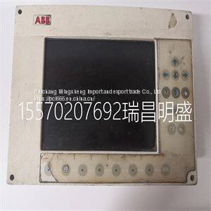
The measure mode is the mode of operation upon transmitter power up and is the normal operating state of the transmitter. In this mode, the PV, output state, fault condition state, spike state, and secondary display information are displayed. All other modes of operation and fault information are accessible from the measure mode. BOREDOM SWITCH When any operating mode or state is entered and the measure mode is not returned to after the final step, the transmitter automatically returns to the measure mode of operation after 20 minutes of unattended use. PRIMARY DISPLAY The primary display shows the PV. The value of this variable is dependent on the configured analyzer, temperature compensation type, temperature value, sensor output, and damping value. The engineering units for the PV are dependent only on the configured analyzer (Table 5-1). SECONDARY DISPLAY The secondary display has the ability to show a large array of information. Since the display area only has six characters, only one item can be shown at any given time. Typically, this region displays the process temperature in degrees Celsius. However, it can be changed to display the process temperature in degrees Fahrenheit, output current in milliamperes, sensor type, cell constant, conductivity value and solute name for a concentration analyzer, or firmware revision. Refer to Section 10 for more information. Fault Information Smart Key Fault information is only accessible from the measure mode of operation. It is interrogated through the FAULT info smart key. Table 5-1. Engineering Units Analyzer Type Engineering Unit Concentration parts per million (ppm), parts per billion (ppb), percent (%), user-defined Conductivity µS/cm, mS/cm MEASURE MODE SECONDARY DISPLAY 5 - 2 WTPEEUI520002A1 A fault condition causes the FAULT icon to blink and the FAULT info smart key to appear. These indicators continue to be present as long as the fault condition exists. When pressing the FAULT info smart key, the faults appear in a first in, first out (FIFO) order and the first fault condition is shown in the secondary display. A short text string followed by the fault code is shown sequentially. Depressing the FAULT info smart key progressively moves from one fault to the next until all faults have been shown. Once all faults have been cycled through, the FAULT icon no longer blinks but remains on until removal of all fault conditions. If a new fault condition is detected, the FAULT icon begins to blink to indicate the newly detected condition. For more information on fault conditions and codes, refer to Section 12 and its related procedures. Menu Smart Key The MENU smart key provides access to all other modes of operation. By pressing the MENU smart key, the transmitter moves from one mode of operation to the next. Visual feedback is provided in two manners: the mode indication arrow moves to the next mode, such as CALIBRATE, and the secondary display shows the text string representative of that mode, such as CALIBR. Access into the displayed mode of operation is allowed by pressing the SELECT smart key. The exit to MEASURE smart key provides an escape function to the measure mode. As seen in the screen flow diagram shown in Figure 5-1, pressing the MENU smart key when in the measure mode moves the transmitter into the calibrate mode. Once in the calibrate mode, pressing the exit to MEASURE smart key returns the transmitter back to the measure mode. Pressing the SELECT smart key moves the transmitter into the calibrate states of operation. Pressing the MENU smart key moves the transmitter to the output/hold mode. Use Figure 5-1 to identify the smart key assignments and the resulting a
>>
Polyester Lining Good Quality Wholesale Unique Design Genuine Leather Wallet for Men at Direct Factory Price
>>
100Pcs Christmas Plastic Bags Xmas Cookie&Candy Self-Adhesive Gift Bag Biscuit Baking Packaging Bag
>>
1970~1981 Camaro Hood Hinge Polished Silver Aluminum Telescopic Chevy Hood Hinge Kit
>>
Customized Label 425g Popular Brand Canned Yellow Peach with Best Price
>>
Gavions gabion box gabion basket gaviones gavione retainingwall seawall riverbank rock PVC coated Gabions 2.7/3.4/2.2
>>
Knife Sharpening Machines Manufacturer in China
>>
Turnover Box Plastic Injection Molding Machine
>>
New and Origina Ls/LG CPU Module GM6-Cpub Made in Korea
>>
Made In China Automated Fabric Waste Fiber Bale Opening Machine
>>
Hot Sale Microfiber Duvet Hotel Comforter Soft 100% Polyester Quilt Duvet with Packaging Bag
>>
OEM Aluminium Expanded Metal Wire Mesh for fence supplier in China
>>
Hot Rolled Galvanized Mild Stainless Aluminum Steel Slitting Line
>>
Welded Steel Wire Mesh Hot DIP Galvanized PVC Coated Garden Panel Iron Metal Fence Fencing
>>
Common Rail Valve FOOR J01 945
>>
Luxury Imported Crocodile Leather Women's Bag High-End Genuine Leather Ladies Shoulder Messenger Bag Chain Bag Square Bag Fashion Small Square Bag
>>
air circulation fan ac industrial blower centrifugal fan manufacturers
>>
Custom Painting Picture Foam Frames PS Photo Frame Moulding
>>
Gold Mining Equipment Sluice Box Dream Turf Grass Artificial Mat Gold Mining Grass Carpet for Washing Plant
>>
2023 High -End Leather Storage Basket Reusable Modern Red Toy Home Storage Holder
>>
Double Shafts Paper/Paperboard/Paper Box/Cardboard/Carton/Waste Milling Machine
