Product Details
Product Description
Product Description
Focus on DCS, PLC, robot control system and large servo system.
Main products: various modules / cards, controllers, touch screens, servo drivers.
Advantages: supply of imported original products, professional production parts,
Fast delivery, accurate delivery time,
The main brands include ABB Bailey, Ge / fuanc, Foxboro, Invensys Triconex, Bently, A-B Rockwell, Emerson, ovation, Motorola, xyvom, Honeywell, Rexroth, KUKA, Ni, Deif, Yokogawa, Woodward, Ryan, Schneider, Yaskawa, Moog, prosoft and other brands
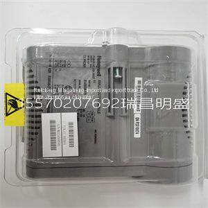
HONEYWELL CC-PAOX01
The measure mode is the mode of operation upon transmitter power up and is the normal operating state of the transmitter. In this mode, the PV, output state, fault condition state, spike state, and secondary display information are displayed. All other modes of operation and fault information are accessible from the measure mode. BOREDOM SWITCH When any operating mode or state is entered and the measure mode is not returned to after the final step, the transmitter automatically returns to the measure mode of operation after 20 minutes of unattended use. PRIMARY DISPLAY The primary display shows the PV. The value of this variable is dependent on the configured analyzer, temperature compensation type, temperature value, sensor output, and damping value. The engineering units for the PV are dependent only on the configured analyzer (Table 5-1). SECONDARY DISPLAY The secondary display has the ability to show a large array of information. Since the display area only has six characters, only one item can be shown at any given time. Typically, this region displays the process temperature in degrees Celsius. However, it can be changed to display the process temperature in degrees Fahrenheit, output current in milliamperes, sensor type, cell constant, conductivity value and solute name for a concentration analyzer, or firmware revision. Refer to Section 10 for more information. Fault Information Smart Key Fault information is only accessible from the measure mode of operation. It is interrogated through the FAULT info smart key. Table 5-1. Engineering Units Analyzer Type Engineering Unit Concentration parts per million (ppm), parts per billion (ppb), percent (%), user-defined Conductivity µS/cm, mS/cm MEASURE MODE SECONDARY DISPLAY 5 - 2 WTPEEUI520002A1 A fault condition causes the FAULT icon to blink and the FAULT info smart key to appear. These indicators continue to be present as long as the fault condition exists. When pressing the FAULT info smart key, the faults appear in a first in, first out (FIFO) order and the first fault condition is shown in the secondary display. A short text string followed by the fault code is shown sequentially. Depressing the FAULT info smart key progressively moves from one fault to the next until all faults have been shown. Once all faults have been cycled through, the FAULT icon no longer blinks but remains on until removal of all fault conditions. If a new fault condition is detected, the FAULT icon begins to blink to indicate the newly detected condition. For more information on fault conditions and codes, refer to Section 12 and its related procedures. Menu Smart Key The MENU smart key provides access to all other modes of operation. By pressing the MENU smart key, the transmitter moves from one mode of operation to the next. Visual feedback is provided in two manners: the mode indication arrow moves to the next mode, such as CALIBRATE, and the secondary display shows the text string representative of that mode, such as CALIBR. Access into the displayed mode of operation is allowed by pressing the SELECT smart key. The exit to MEASURE smart key provides an escape function to the measure mode. As seen in the screen flow diagram shown in Figure 5-1, pressing the MENU smart key when in the measure mode moves the transmitter into the calibrate mode. Once in the calibrate mode, pressing the exit to MEASURE smart key returns the transmitter back to the measure mode. Pressing the SELECT smart key moves the transmitter into the calibrate states of operation. Pressing the MENU smart key moves the transmitter to the output/hold mode. Use Figure 5-1 to identify the smart key assignments and the resulting a
>>
Trough Shaped Detergent Powder Mixer Machine
>>
Crane manufacturer 20 Ton Crane Mounted Truck folding arm crane truck
>>
Travel Switch Yblx-P1-/120/1g for Hls120 Hls180 Concrete Mixing Batching Plant Spare Parts
>>
110cc New Model Cub Fenghao Type Moto / Motorcycle /Motorcycle
>>
century 285cm fishing rod baitcasting fishing rod 702m 7mtrs dawa fishing rod price
>>
China Small 200 Liter Industrial Dry Powder Food Chemical Medicine Granule V Type Blender Mixer Machine
>>
HC-S106 New multifunctional nursing internship model/nursing manikin/simulator(female)
>>
100-120HP Matched Power Corn Precision Fertilizer Seeder
>>
#62078 ATV Cast Iron Cultipacker Wheel, 9-1/2 Inch for USA
>>
7 pieces pressure cooker caldero pot aluminum cookware set
>>
3D LED Crystal Cube/Trophy/Keychain/Craft Gift/Glass Ball with CCD Camera Human Portrait Photo Inside Subsurface CNC Laser Engraver Engraving Machines Price
>>
Warehouse Industrial Heavy Duty ISO Plastic Pallet for Storage
>>
Lm25141qrgerq1 switch controller Ti original stock
>>
1tons Per Hour Cat Litter Production Line Pellet Machine for Tofu Bamboo Charcoal Cat Litters
>>
Feeds Pellet Maker Machine Animal Food Pellet Machine Peletizadora De Alimento Animal
>>
Paper making machinery Craft paper,Test liner
>>
Hot Sale Suspension Leaf Spring Truck Trailer Leaf Spring Rear Leaf Spring for Semi Trailer Part and Auto Spare Parts
>>
Factory Automatic Sheet Feed Hot Foil Stamping Machine JXC-75
>>
Fiber Glass Tuna Rod, Tuna fishing (Jack) Pole
>>
Preservation for Water-based Synthetic Metal Working Fluids GreatAp126 Sterilization and Anti-corrosion Biocide
