Product Details
Product Description
Product Description
Focus on DCS, PLC, robot control system and large servo system.
Main products: various modules / cards, controllers, touch screens, servo drivers.
Advantages: supply of imported original products, professional production parts,
Fast delivery, accurate delivery time,
The main brands include ABB Bailey, Ge / fuanc, Foxboro, Invensys Triconex, Bently, A-B Rockwell, Emerson, ovation, Motorola, xyvom, Honeywell, Rexroth, KUKA, Ni, Deif, Yokogawa, Woodward, Ryan, Schneider, Yaskawa, Moog, prosoft and other brands
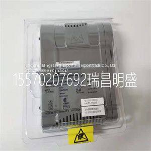
HONEYWELL CC-PCNT02 M0200705321
The measure mode is the mode of operation upon transmitter power up and is the normal operating state of the transmitter. In this mode, the PV, output state, fault condition state, spike state, and secondary display information are displayed. All other modes of operation and fault information are accessible from the measure mode. BOREDOM SWITCH When any operating mode or state is entered and the measure mode is not returned to after the final step, the transmitter automatically returns to the measure mode of operation after 20 minutes of unattended use. PRIMARY DISPLAY The primary display shows the PV. The value of this variable is dependent on the configured analyzer, temperature compensation type, temperature value, sensor output, and damping value. The engineering units for the PV are dependent only on the configured analyzer (Table 5-1). SECONDARY DISPLAY The secondary display has the ability to show a large array of information. Since the display area only has six characters, only one item can be shown at any given time. Typically, this region displays the process temperature in degrees Celsius. However, it can be changed to display the process temperature in degrees Fahrenheit, output current in milliamperes, sensor type, cell constant, conductivity value and solute name for a concentration analyzer, or firmware revision. Refer to Section 10 for more information. Fault Information Smart Key Fault information is only accessible from the measure mode of operation. It is interrogated through the FAULT info smart key. Table 5-1. Engineering Units Analyzer Type Engineering Unit Concentration parts per million (ppm), parts per billion (ppb), percent (%), user-defined Conductivity µS/cm, mS/cm MEASURE MODE SECONDARY DISPLAY 5 - 2 WTPEEUI520002A1 A fault condition causes the FAULT icon to blink and the FAULT info smart key to appear. These indicators continue to be present as long as the fault condition exists. When pressing the FAULT info smart key, the faults appear in a first in, first out (FIFO) order and the first fault condition is shown in the secondary display. A short text string followed by the fault code is shown sequentially. Depressing the FAULT info smart key progressively moves from one fault to the next until all faults have been shown. Once all faults have been cycled through, the FAULT icon no longer blinks but remains on until removal of all fault conditions. If a new fault condition is detected, the FAULT icon begins to blink to indicate the newly detected condition. For more information on fault conditions and codes, refer to Section 12 and its related procedures. Menu Smart Key The MENU smart key provides access to all other modes of operation. By pressing the MENU smart key, the transmitter moves from one mode of operation to the next. Visual feedback is provided in two manners: the mode indication arrow moves to the next mode, such as CALIBRATE, and the secondary display shows the text string representative of that mode, such as CALIBR. Access into the displayed mode of operation is allowed by pressing the SELECT smart key. The exit to MEASURE smart key provides an escape function to the measure mode. As seen in the screen flow diagram shown in Figure 5-1, pressing the MENU smart key when in the measure mode moves the transmitter into the calibrate mode. Once in the calibrate mode, pressing the exit to MEASURE smart key returns the transmitter back to the measure mode. Pressing the SELECT smart key moves the transmitter into the calibrate states of operation. Pressing the MENU smart key moves the transmitter to the output/hold mode. Use Figure 5-1 to identify the smart key assignments and the resulting a
>>
High Efficiency Small Roller Type Coal Powder Mineral 7-10t/H BBQ Egg Oval Pillow Shape Press Briquette Charcoal Making Machine
>>
High Quality Hot Sale 52cc Loosener 2 Stroke Weeding Machine Mini Tiller
>>
10m Electric Motor Driven Self Propelled Scissor Lift Platform
>>
Reinforced Mesh Welding Machine Construction Reinforced Mesh Welding Machine Concrete Reinforced Mesh Welding Machine
>>
Manufacturer Disposable Protective Mask Face Shield
>>
High Efficiency Animal Feed Mill Grinder Corn Hammer Mill
>>
Yujian High-Performance 50 Needle Shirring Machine for Tailoring
>>
High Quality Dental Suction Machine Medical Dental Equipment
>>
New Child Safety Pet gate for Stairs, Pet Safety Protection Room Divider Gate
>>
CE; ISO; SGS Horizontal Shenzhou Standard Export Wooden Box PVC Pipe Fitting Machinery Molding Machine
>>
PIB671-1500 ABB Advantage system metering board
>>
China Quality Wholesaler TRACKER/TRAX car Rear wheel housing liner LH For Chevrolet 95142655
>>
Rexroth Gft Series Final Drive Gearbox Gft110t3 Series
>>
Wooden Single Level Easel (W15)
>>
All Size Laser Welded Diamond Cutting Disc for Stone Asphalt and Concrete Diamond Saw Blade
>>
China Most Professional Fully Intelligent Cotton Candy Machine for Sale in Bulk
>>
Concrete and Reinforced Concrete Products Vibration Table
>>
Spinning Machine Textile Accessories Parts
>>
Solder End to SMA RG178 Cable, Solder Bifurcated Connector to SMA Female
>>
OEM 24407484 5636324 Timing Gear for Opel Vectra 2.2 Engine Z22YH TG1045
